*This post was originally written April 12, 2019
_______________________________
Solar! The concept itself is exciting and empowering. And I had a plan.
But – that plan changed – several times. In this blog post I describe the many iterations of my planned solar install, the size of my set up, materials, and other considerations.
To be clear: I am not an electrician. I spent an enormous amount of time researching this phase of my build, until I felt comfortable with my plan, and if you are looking to do something like this I encourage you to research the hell out of electrical! I’ve found it helpful to accumulate several sources for info, as experiences, materials, and opinions vary.
Layout
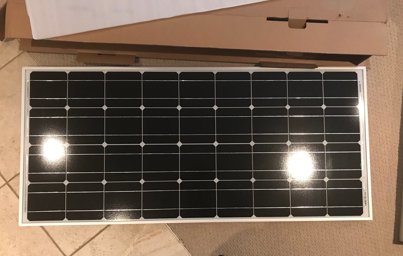
When I first sat down to research my van build and prepare for the journey that it has become, I figured I would do what many seemed to do and bolt solar panels directly to my van’s roof (or a version of this) – if it worked for other people it could work for me! I based my plans on this decision – the panels, the supplies I would need to purchase (including length and gauge of wiring, mounting brackets for attaching to the roof, and hardware), and the general layout.
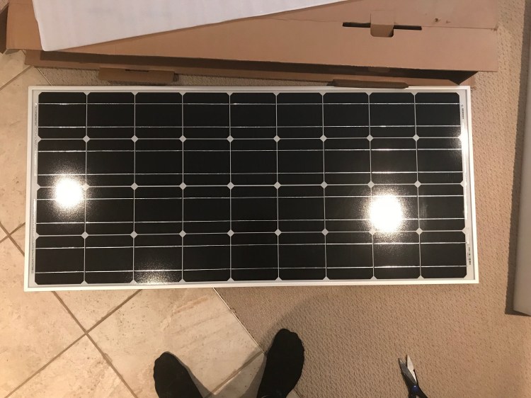
I bought the things and I started the build. Solar wasn’t first on my agenda, so the things sat and I compartmentalized, forgetting about them for the moment (though goggling at them in awe – mostly the panels – when they arrived in the mail).
But as I worked on the van, and after installing the fan (aka cutting a big hole in my roof) – I decided I was not keen on the idea of putting more holes in my roof in order to attach solar panels. In the back of my mind I wondered if a day would come when I would like to sell my van (I don’t know that I will be able to part with it after putting all this work in and travelling in it, but I like to keep my options open) – and lots of holes in the roof could certainly be a deterrent. Plus, I would have to continually monitor for leaks and touch up sealant (related: many people swear by cable entry housing). It could work – and I am sure it has worked well for many out there – but it was quickly becoming a “no go” for me.
Side note: If I had gone ahead with this installation, I was planning to perform a “leak test” afterward (ideally after both solar and the fan were installed) to ensure that everything was fully sealed.
My next plan incorporated the roof rack that my van had come with when I bought it. It was a good quality stainless steel rack.
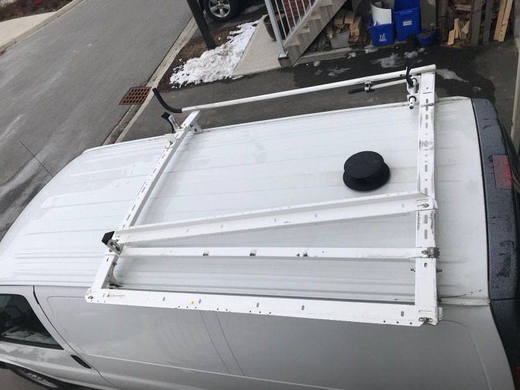
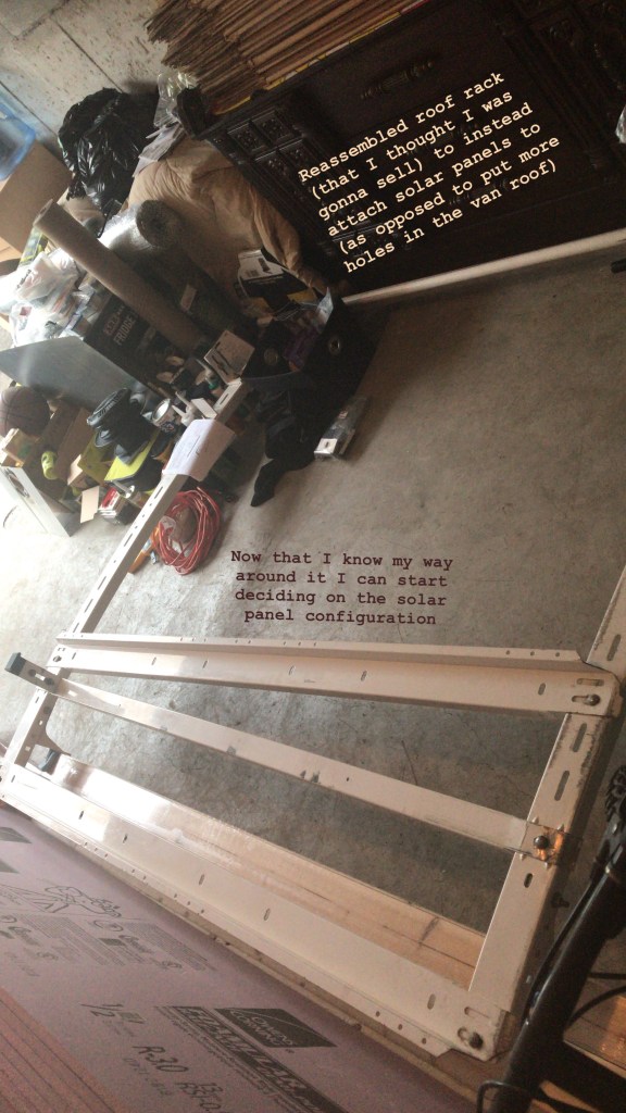
But when I tried to dry fit the panels to it I ran into an issue I could not overcome – the proportions and design of the rack. The support rails that crossed the van body were thick steel and sturdy – ideal for placing the weight of my panels (16.5 lbs each) on – but they had a slight curve to them, meaning my panels would not lie flat. I could probably work around this, but the rails that attached lengthwise between these support bars only attached in a way that had the support arms about 6 feet apart – and my panels were only 4 feet long. I considered placing the panels on angle bars and fastening these angle bars to the support rails. Or I could potentially only use the support racks in my configuration – but then I got put off by the idea of wind resistance.
This roof rack is about 6 inches above my roof, creating a space for air to flow under the panels, which could create lift (the image of panels being ripped off a moving van on the highway flit through my mind). And also drag, which would ultimately impact my mpg.
I considered creating a make-shift attachment that I could put in front of the rack on a 45 degree angle that would direct air over the rack and create a more aerodynamic structure – but I thought there must be a better (simpler) way. I researched online for the perfect roof rack for my van, and while I fell in love with the Aluminess racks and accessories, I couldn’t justify the price at this time. I’d seen a few people who made similar racks themselves for way cheaper. In the future this might be something I consider (the van build is never finished – upgrades and fixes are imminent!). Especially because there are other upsides to having a roof rack. It gives you more space to carry belongings and can be used to attach an awning!
Another option was using gutter mount racks the way Bob of Cheap RV Living did (making a wood platform to screw panels into), or how Adventure Van Man did (using angle bars and U-bolts). Above all else reliability and quality were my number one concerns here as these things were going to be riding outside the van at high speeds. There was another option though…
Adhesive. Predominantly, VHB tape. From all accounts, if installed correctly, VHB (Very High Bond) tape can work wonders. It is replacing the need for conventional fasteners in many applications. It holds up skyscraper windows. And I’ve seen reviews online of van lifers and RVers who had used only VHB tape to attach their solar panels to their vehicle roofs, updating as time passed, to conclude that their panels remained secure. It would be tricky with my slightly curved Chevy Express roof, but I could make it work if I placed my two panels along the centre of my roof like a van mohawk… Though another consideration is the flexible nature of my roof – the panels may not be fully supported by the ribs inside the van, depending on where the mounting brackets are placed – support is meant to provided by a rack secured to the gutter mounts of this van.
I have also seen people use other forms of adhesive, including Jed of Into The Mystery 13, who used Sikaflex in one of his installations. In the end I was a little too nervous to use an adhesive, but it was definitely a contender in my war on panel installation.
Note: it is recommended that if you are going to adhere your panels using a form of adhesive that you follow all manufacturer instructions (for example sanding your surface, cleaning it with rubbing alcohol, and installing at optimal temperatures). It is also a good idea to have a back up in place – such as the panels secured to something with a UV protected safety rope in case your adhesive does fail. Many people also put Eternabond tape over their mounting feet.
If I were to go the adhesive route, I would probably use the mounting brackets from Renogy, VHB tape (4950), Eternabond tape placed over the mounting bracket feet and Dicor self-levelling lap sealant on the inner edges to create a barrier between any moisture and the VHB tape. Plus put the support rails of my roof rack up and secure my panels together as well as to the roof rack with weather resistant rope.
All of this back and forth got me pretty frustrated, which led to my fourth and final solution for my power set up…
I wasn’t going to install solar panels at all…
Now, this kind of goes against my perceived aesthetic of a true van-life van. But, roof fan aside, not putting panels or a rack on my roof would somewhat aid in stealth, certainly cut down on wind resistance (preserving what little fuel efficiency I do have), and at the end of the day attract less attention to my van (including from that of thieves) and eliminate any fear of the panels coming loose.
*Now my plan is to get portable panels (like a solar suitcase) and use them to charge my battery whenever I am parked for long periods (like at a campground or on BLM land). This will allow me to park in the shade, place the panels in the sun, and angle them however I like. If I’m not with my van (e.g., hiking) I want to make mounts on my roof where I can lock my panels on to prevent theft and charge my battery while I’m out for the day. To make this charging option even better, I want to charge my power station’s battery from my van while driving from place to place.
For some, the thought of putting panels out and taking them in all the time might be a downer – having them permanently installed on your roof means you can (almost) forget about them. I completely understand that point of view. But for me – this is my favourite option at this point in time. Who knows, maybe in the future I’ll save up and get myself an Aluminess rack. But for now, this is what I’ll be doing.
Phew! I don’t think I can possibly convey adequately how many hours of research and rethinking and frustration and consideration and changing my mind and just wanting a solution – went into this plan. Glad that’s finally sorted!
*Fun fact: If I were to one day put panels on my roof, there’s a neat trick I learned for avoiding damage to electronics if a leak should occur. Offset the hole into the van and wiring so that they are not directly above any electronics and create a “drip loop” bend in the wire so that if there is a leak it will drip off the wire before getting to your attached electrical appliances. This won’t save your roofing from possible rust or mold that might result from a long term leak, but it will save some expensive equipment from untimely damage or death.
Configuring My Solar Power System
This was the first thing I did – before I continually changed my mind about my layout. While researching the build and compiling a list of supplies I would need to buy, I needed to figure out my electrical needs, which would determine the size of my power set up and what materials I should purchase.
Energy Consumption
So how much energy could I reasonably expect to consume daily? Knowing this would set the foundation for what components my system would need in terms of size and capacity. To determine this I had to know exactly what I was planning to have in my van.
I figured I would probably fall in the mid-range of consumption from what I’ve seen online. Some people use their campervans similar to a tent – preferring to remain disconnected and go the more natural route. Others are nomadic entrepreneurs who make a living on the road or just enjoy more comforts that can only be provided with electricity. To each their own!
So what will I be packing? My main sources of energy consumption will be my fan, fridge, lights, phone, computer, and possibly a small toaster oven. That being said, I can stick to natural lighting (I also really want to get a lantern, and may use candles – with extra care), and I want to limit my use of electronics. The toaster oven was an idea at the outset of my research but I am not sure I’ll actually go with it now.
The next step in designing my set up was using these loads to calculate how much power I could reasonably expect to use daily, which in turn would inform me of what size battery I would need to buy. To do this I followed a nifty calculation that I found (Renogy and Gnomad Home also walk you through some calculations):
(W)(hrs) = Wh, Wh/12V = Ah
The first step was to figure out the wattage on which each item operates. This will typically be labelled on each item, but since I was doing preliminary calculations and didn’t have everything yet, I looked for these values online – in online manuals, product descriptions, and even the Amazon “questions” section.
Next up, I estimated how many hours per day I thought each item would be hooked up/ drawing power/ charging. Keeping in mind that I’ll be operating on a 12V system, I plugged all these values into my calculation to attain Amp hours (Ah). Basically, this is how much battery capacity I’ll be using in a day. And a good general rule is that whatever you think you’ll use, double it to get an idea of what size battery you’ll need in your system.
Why? Because you never want to fully drain your battery or you can cause permanent damage to it. Most lead acid batteries should only be discharged by 50% at most. You can get deep-cycle batteries and lithium-ion that allow for a larger discharge before possibly damaging the battery, but to be safe, 50% discharge is a good goal to have. If you’d like to read more about batteries, here is an article I found extremely informative. And in the case of creating my power set up, I would rather overestimate my needs than underestimate them (though on the bright side if I do underestimate, it’s a learning experience and can push me to learn how to be conservative, which is certainly a good skill to have!)
Here’s what my initial calculations looked like:
- MaxxFan 6200K – (24W)(18hrs) = 432Wh/ 12V = 36Ah
- ARB Fridge 50Qt – (24W)(24hrs) = 576Wh/ 12V = 48Ah
- LED Rope Lights – (8.5W)(12hrs) = 102Wh/12V = 8.5Ah
- Phone – (5W)(1hr) = 5Wh/ 12V = 0.42Ah
- Computer – (16.5V)(3.65A) = (60.225W)(1hr) = 60Wh/12V = 5Ah
- Toaster Oven – (500W)(0.5hr) = 250Wh/12V = 20.83Ah
- Total Daily Consumption: 118.75Ah x 2 = 237.5Ah goal battery capacity.
That’s a big battery!
But here are some comments on those first calculations. They’re not going to be fully accurate because they are an estimation. I also did not take into consideration losses that would be incurred through the inverter used to charge my AC devices like my phone and computer. Also, I do not have my lights yet, so I can’t say for sure what their draw will be. I may not get a toaster oven. And the fan and fridge calculations are likely overestimations. I found a page that breaks down the (Deluxe) MaxxFan’s consumption based on what speed you’re using it at, and it looks like this:
- Speed Amp
- 1 0.1
- 2 0.2
- 3 0.3
- 4 0.4
- 5 0.6
- 6 0.9
- 7 1.1
- 8 1.5
- 9 2.0
- 10 2.8
*As you can see, based on my initial calculations I am assuming the fan would be running at 2Ah – equal to speed 9, which I doubt will be the case!
In terms of my fridge, different studies have quoted different consumptions. Apparently, the stated power draw ranges from 0.7 – 2.3Ah, with an average tested power draw of 0.87Ah. (Check out Gnomad Home’s amazing spread sheet for specs on all sorts of fridges!)
So with these considerations in mind, a more reasonable calculation (taking variations into account and making arbitrary estimates to account for error) might look like this:
- MaxxFan 6200K – (1A)(18hrs) = 18Ah
- ARB Fridge 50Qt – (1A)(24hrs) = 24Ah
- LED Rope Lights – (8.5W)(12hrs) = 102Wh/12V = 8.5Ah
- Phone – (5W)(1hr) = 5Wh/ 12V = 0.42Ah
- Computer – (16.5V)(3.65A) = (60.225W)(1hr) = 60Wh/12V = 5Ah
- Toaster Oven – (500W)(0.25hr) = 125Wh/12V = 10.42Ah
- Total Daily Consumption: 66.34Ah x 2 = 132.68Ah goal battery capacity.
I will also mention that I’ve read that the fridge cycles between “on” and “off”. References to power consumption studies I’ve read don’t state whether their “average” power consumptions take this into account (though I’m thinking that’s why they give a range and that is indeed what they mean by average). How much energy is being drawn would also be based on the ambient temperature – more energy draw in warmer climes.
*All in all, I am happy with this second round of calculations. For me, I still think they are an overestimation and that should account for any error. Plus – with a lithium-ion battery I will be able to discharge at about 80% rather than 50%, giving me another 30% extra wiggle room. And in the event that I do need to conserve energy I can easily set the fan to a lower setting, not use my lights as much, only charge my phone while I’m driving, restrict computer use to cafes, and I’m not even sure I’ll get the toaster oven!
Materials
So now that I had an idea of my energy consumption, I was aiming for a battery size of about 133Ah. And this was my starting point for figuring out the rest.
I could go the route of building my own system from scratch – buying each component separately (battery, inverter, charge controller, isolator) and wiring everything myself. When it comes to a van build, the concept of DIY is central, and the electrical set up is probably the most demanding and “brag-worthy” component. I would love to be able to say that I built my whole electrical system from scratch. BUT I think there is no shame in admitting when you are out of your league – and electrical is not something I want to take any chances with. That being said, I think if I really wanted to do it – I could. Especially now that some time has passed since I researched all of this and I have some of the build under my belt. But I am not an electrician and have minimal experience in the electrical world. So I aired on the safe side and went with a “plug and play” power station – battery, wiring, charge controller, inverter all included in one neat box.
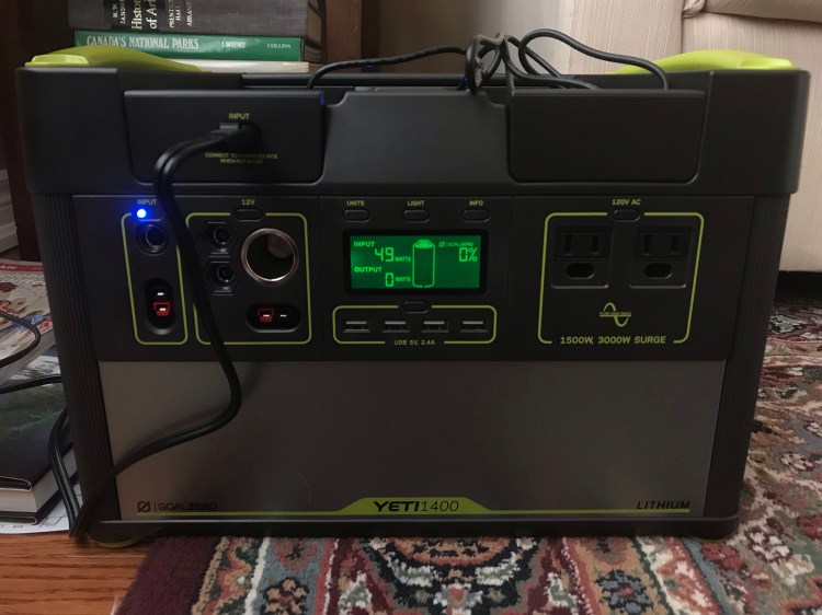
Goal Zero vs. Inergy Kodiak
From what I can tell – there are two big players on the power station market: Goal Zero and Inergy (Kodiak). I hadn’t heard of the Kodiak (now Apex) until after purchasing Goal Zero’s Yeti 1400 Lithium Power Station.
I stumbled across a couple of in depth reviews by some guys I consider well versed in the mobile living/ solar world (here and here). And their conclusions were the same: Kodiak was the better option. Typical of a van build – I was second guessing my decision after the fact.
The stand out reasons for choosing the Kodiak are that charge time is much faster and the battery is rated for 2,000 lifecycles (or 10 years), while the Yeti by comparison only has 500 cycles to 80%. I dug in and did my research and the Kodiak really did look like a winner – if I were to do it again I would probably go with Inergy!
Apart from why others’ reviews claimed Kodiak to be better, I wanted to be able to charge my battery from my van while driving. Kodiak allows you to do this – but Goal Zero did not. And this really set the two apart for me.
It was too late for me to return the Yeti, so I had two options. I could either try and sell the Yeti, likely lose a bit of money, and then buy the Kodiak. Or I could suck it up, stick with the Yeti, and find a way to install solar panels on my roof.
*Then something magical happened. I got an email from Goal Zero recently informing me that they had just released a new 12V car charging cable (February 2019) that allowed for charging the Yeti from your vehicle.
I emailed Goal Zero to get more information. I’d read that it’s not a good idea to charge a lithium battery from a lead acid battery, and my Yeti manual says, “IMPORTANT NOTE: The Goal Zero Yeti Lithium is not compatible recharging from a 12V source, it can result in damage to the unit, cable, as well as your vehicle.” Needless to say, I was curious as to how this cable differed. Here’s the response I got:
“The whole reason we advertised the Yeti lithiums not being able to charge from a 12v source was because of the old car charger we had available. This old car charger is what caused the danger, not the Yeti. The old car charger was not able to handle the amount of power the Yeti lithiums would pull from your car. This would result in the car charger cable melting or fuses blowing within your vehicle. This new car charger is made to handle the correct voltages and also has fuse protection built in. You can safely charge your Yeti lithium unit with this cable without any worries of damaging your Yeti or your vehicle.”
Other info about charging that I received: “If your car outputs more than 120 watts, the car charger will simply step down the power going into the Yeti,” and “With the 1000 charging from this car charger, you will recharge the 1000 in about 8 hours. (1000capacity/120watts of input= 8.3 hours of charging).” Thus my Yeti 1400 would reasonably be believed to charge in 1400/120 = 11.7 hours.
Side note: here is a little article that talks about car accessory outlets. Typically, car cigarette lighters have a 15 amp fuse. With a 12V system and (V)(A) = W, the vehicle’s fuse would blow at 180W. Since Goal Zero’s car charger pulls 120W (12v and up to 10A; also the max input rating on the Yeti’s 8mm input ports), this should be compatible. I consulted my mechanic and he was able to pull up a schematic of my specific van’s electrical system, which showed that I have a 20A fuse on my accessory outlet (he also showed me where the fuse box is under the hood, which labels what each fuse is for and you can see their amp rating). Therefore, I would have to hit 12V x 20A = 240W to blow it.
Side by side, the Kodiak might still have been my first choice, but having a car charging cable now made the prospect of selling my Yeti a hassle that just didn’t feel worth it anymore. Goal Zero does sell replacement batteries for their power stations, though no price is listed on their website. There was also the battery capacity to take into consideration. Kodiak sells their power stations with 90Ah batteries, while the Yeti 1400 is at 132Ah. The Kodiak/Apex are chainable, so you can attach batteries (external Lithium-Ion, 12V lead acid or AGM deep cycle) for more capacity. But I would do more research into expanding with external batteries before settling on that method (and if I were to chain, I would use lithium ion). Here’s a blurb from my research notes explaining why (source unknown):
- Note that the issue with chaining AGM batteries to a Kodiak is that the Kodiak has no built in protections to make sure the AGM does not get too low – and you are not supposed to go below 50% charge or risk permanent damage… The Kodiak shows charge in Volts on the display screen – A fully charged Kodiak will be between 12.3 – 12.6 Volts. A completely discharged Kodiak will be between 9.3 – 9.6 Volts. So about 11V is 50% charged. The Kodiak software will equalize the internal battery voltage with any external batteries that are connected. AGM manufacturers state not to let the battery go below 50% – this is if using the battery for its intended function, i.e., starting a motor ECT. However since the Kodiak is only using the battery as a power cell, and not needing to draw high cranking AMPS this will only shorten the AGM’s life by a few charge cycles. This does mean however that the external battery will only be good to be used with the Kodiak. Also to take into account that if you can only use half the battery power… 80% of the Kodiak’s 90Ah = 72Ah you can safely use, while 50% of 90Ah + 100Ah external AGM = 95Ah total.
If this is true, what concerns me here is that if you chain one 100Ah AGM you would have to continually monitor to make sure both batteries do not go below a 50% charge (11V on the Kodiak) – which means that you are not using the full Kodiak potential, and you end up with only 23Ah extra than with the Kodiak alone.
While I think I could manage on a 90Ah battery if I conserved energy, the larger 132Ah Yeti battery that I already own is more attractive now.
*In the end, the new Goal Zero car charging cable seems to be a god(dess)-send and I am happy sticking with what I’ve got.
Solar Panels
I did a lot of research into solar panels – type and brand. Ultimately, Renogy was the brand I felt to be most reliable, rigid panels came ahead of flexible, and monocrystalline beat polycrystalline.
I chose Renogy because of reviews, they came up a lot when I explored what other van lifers or bloggers were using, and they have a 25 year warranty on their rigid panels – which I think speaks for itself. To me, this all spelled out quality.
While I really wanted to love flexible panels (they’re so convenient!), I just couldn’t ignore the cons to using them. First off, they’re more expensive than their rigid panel counterparts. Because of their flexible construction, they don’t have as much protection as the rigid panels (e.g., if you bend them too far you may hear a crunch – which has damaged the cells). The big pro to using them is for their sleek design which is a huge advantage for those who want to be stealth – and preserve aerodynamics. With this in mind the ideal installation entails having the panels flat against another surface (like your roof top) – but solar panels need about an inch of air space below them to prevent overheating (which decreases efficiency and can cause damage). People have documented experiences with flexible panels where they stop working efficiently after only a year (or less), and develop hot spots, damaging the cells. Rigid panels do not display these problems – and in fact that’s why their warranty period is so long!
I heard that in the past Renogy had run into problems with their flexible panels – they handled it well, replacing panels for their customers at no cost, but it ultimately caused them to take their flexible panels off the market. They currently do sell flexible panels and I was surprised to see that the warranty on these are also at 25 years. So if I were to try any flexible panels – these would be the ones I’d go with, knowing that a reputable company is backing them.
While polycrystalline panels are often cheaper, monocrystalline panels are of better quality. You can read more here (along with some solar panel reviews).
Other than that I had to consider how many panels I would need. I settled on 2 x 100W rigid panels from Renogy. I read that a good general guideline is to match your solar panel wattage to your battery capacity – so for a 132Ah battery I would want at least 132W in solar panels.
Of note is that the Yeti has two 8mm input ports that can handle 120W each (for a maximum of 240W; one of these ports is located under the lid) and one Anderson PowerPole input port that can handle a max of 360W input itself, which is also the max input across all input ports. So I would not be able to exceed 360W with my solar panels. The more solar panels you have, the quicker the charge time of your battery, and the more you can charge in weather that is not ideal – like on cloudy days (where panels generate electricity at about 20% of direct sunlight output).
Also important to note is what max voltage input your system can handle. This ties into what charge controller you have. Because my Yeti has a PWM controller, the manual states that it can only handle a max solar input of 22V, either from a single panel or if wired in series. This information is written in bold in my Yeti manual. When I took a closer look at my panels’ specifications I saw that the Optimum Operating Voltage (Vmp) is 18.9V and the Open-Circuit Voltage (Voc) is 22.5V – exceeding Goal Zero’s max 22V rated input.
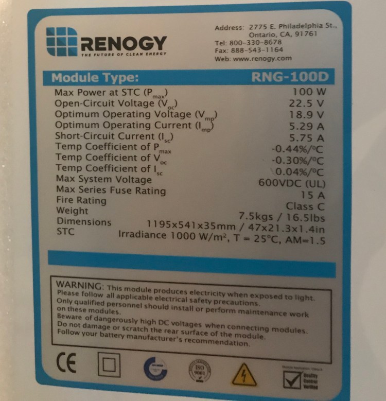
Side note on Voc: I contacted my cousin, who works as an electrician to ask about this. He recommended having a power station with a higher voltage rating to ensure it is not overloaded. So with these particular panels I’d want a power station able to handle a Voc of at least 28.125V. “Any electrical device that is subject to continuous use such as a panel charging station being charged by solar panels during the day should be rated so the load, or in this case the source, will only use 80% of its capacity. Your panels have an open circuit voltage of 22.5V so your charger needs to be rated for 22.5 x 1/0.80 = 28.125V minimum.” He explained that optimum voltage (18.9V here) is the voltage you would see when your power station is under full load, whereas open-circuit voltage is what would be observed when charging but no load is being used.
According to the manual for my Renogy 100W panels: “Under normal conditions, a photovoltaic module is likely to experience more current and/or voltage than its Standard Test Condition’s rated output. Accordingly, the values of Isc and Voc marked on this module should be multiplied by a factor of 1.25 when determining component voltage ratings, conductor ampacities, fuse sizes, and size of controls connected to the PV output.” Thus we would look at 22.5Voc x 1.25 = 28.125 – the same as my cousin suggested.
I spoke with a few Goal Zero reps who stated that I do not need to be concerned with the Voc, that it is the optimum operating voltage that is important. I’m the kind of person who needs to know why, so I mulled it over some more. My thought process was that if the optimum operating voltage occurs when there is a load and the Yeti, when recharging, is a load on the panels, then the set up should always be operating at the optimum voltage. And in terms of when the Yeti is fully charged (which if I’m being honest will probably be rare on the road), I believe the Yeti has overcharge protection – it will stop charging input when full. I called Goal Zero to confirm this, and I was right. The Yeti stops power flow once fully charged – so in theory the panels should never charge the Yeti at their Voc of 22.5V. I also called Renogy and they explained it as the panels only measuring at 22.5V (Voc) when the circuit is open, but once you close the circuit (connect to the Yeti) the voltage will drop down to it optimum operating value (in this case 18.9V).
It always pays to be safe, and if I was putting together my own system from scratch I would factor in the 1.25 safety calculation when choosing my components. But with a consensus from the technical support reps from both companies, I am comfortable with my set up.
Connections
Parallel vs. Series Wiring
In terms of how the panels are wired, there are two options: in parallel or in series (some people may do a combination but that’s typically for larger systems). Basically, when you wire in parallel you are connecting all positive terminals together and all negative terminals together which keeps the circuit at 12V and has an additive effect on amperage. This means that charging remains at 12V for your 12V system. The downside to parallel seems to be in the case of running long lengths of wire – in which case you would need a larger gauge wire which can get expensive. Also, needing special connectors. Wiring in series instead connects positive to negative terminals and preserves amperage while adding together voltage (in which case an MPPT charge controller would best a PWM charge controller). The downside to series is that all panels sort of “think as one” – which can create an issue if any of the panels are in shade as it will affect the whole system – an issue that does not exist with parallel wiring.
For me, the Goal Zero Yeti specifies that solar panels connected to it must be wired in parallel in order to keep the voltage at 12V – if I were to wire in series the voltage of the circuit would increase beyond the capabilities of the Yeti. More information on parallel vs. series wiring can be found here and here.
Charge Controllers: MPPT vs. PWM
Even if, like me, you’re not building your own system from scratch, your power station should have a charge controller in it, and this might affect your decision on which component to invest in. Charge controllers regulate the energy going from solar panels to your battery. According to Renogy, MPPT (Maximum Power Point Tracking) charge controllers can handle a higher voltage, and therefore can handle in series wiring of solar panels, while still being able to charge 12V batteries. But my Yeti has a PWM (Pulse Width Modulation) charge controller, which can’t handle higher voltages, thus accounting for the required parallel wiring. Inergy on the other hand makes their solar generators with MPPT charge controllers. For a breakdown of PWM vs. MPPT you can go here.
Connecting The Dots
All that’s left to do now is connect everything up. I needed to figure out specifically what kinds of cords/ cables/ wires, fuses, and connectors I’d need to bring everything together.
With my plug and play set up, I didn’t need to do as much here as those who built their electrical systems from scratch. But I did still need to acquire a general understanding of wire gauge, fuses and connectors.
Wires
I used this website to calculate my wire needs based on wire length, volts, and (max) amps for each component of my system. This is also an informative page. For example, when taking into account wiring for my MaxxFan I estimated I would need 22 feet of wire (if the fan is about 11 feet from where I’ll connect it to my power station, factoring in the positive and negative wires – I have to double the distance). Voltage is easy as it’s a 12V system. And max amperage is 5 amps. When I plugged this into the above linked calculator I got a result of 14 AWG wire.
Note that the Circuit Wizard calculator allows you to specify the voltage drop (losses due to resistance of current flowing through a conductor) – which you want to aim to be equal to or less than 3%. I’ve read that up to 5% voltage drop is okay, and I’ve read that 2% is the goal. Opinions vary. But my understanding is that voltage drop holds more weight in a 12V DC system than it does with AC. Also, the more voltage drop you have, the less efficient your system will be for charging your battery. And finally, voltage drop can cause overheating due to the friction/ resistance – and preventing an electrical fire is a top priority. If you want less voltage drop use a higher gauge wire. Shorter cables also reduce losses.
*In terms of the wiring from my solar panels to power station, because of the parallel wiring I needed to purchase special connectors. Renogy uses MC4 connectors on their panels. Since I bought two of their panels I got two MC4 branch connectors. This takes the two positive wires (one from each panel) and two negative wires and turns them into one positive and one negative. I got two extension cords to attach here – each 10ft and 10AWG.
Ideally, I would have liked to get 8AWG cables as my current set up requires longer cable runs between the solar panels and battery. Even 6AWG was suggested by the calculator in longer runs. Unfortunately, since I am using MC4 connectors (Renogy uses these), wire gauge is limited to 10 or 12AWG – something about MC4s only being compatible with these sizes. Ten and 12AWG are the only options on Renogy’s website for extensions and while I searched Amazon and found an 8AWG option, they were more expensive and had variable reviews (mostly good, but some issues hard to ignore). I ended up compromising – opting to shorten my cables, which will give me less flexibility and slightly increase my voltage drop (probably 4%), and stuck with Renogy. In an ideal world I would always go bigger on wire gauge, but a van build is filled with tough decisions.
All of this being said, calculations can vary out there. To use the Circuit Wizard Calculator, you need system volts, max amperage, and length of wire run.
Voltage = 12V.
Max amperage – One way of estimating is by taking the total Watts and dividing by 12V. For me, 2 x 100W solar panels = 200W/12V = 16.67A. Another way of doing this is to take the short-circuit current (Isc) of the panels (for the Renogy 100W this is 5.75A x 2 panels = 11.5), add 25% to this value to account for possible exceeded standard test values (factory ratings can be exceeded in real life situations) – this is an industry standard (11.5 x 1.25 = 14.375), and add another 25% to account for a continuous load as required by the National Electrical Code (NEC), giving us a total of about 18A. . But I have also seen calculations where it is not this max amperage used, but the typical/ expected/ normal operating amperage. In this case 2 x Optimum Operating Current (Imp) of 5.29A = 10.58A. Could using this value work? Honestly, I like to play it safe, so i used the highest calculation for max amperage.
Length of wire: This step I found a little tricky since I have multiple wires going from the panels to the battery. First are the 12AWG wires connected to the panels already. The there is the MC4 to Anderson Power Pole adapter cable that will connect my solar cables to the Yeti. Then, finally in between these are my extension cables. So – which ones do I use in my calculations? I opted to leave out the 12AWG cables coming off the panels. Especially since my calculations are taking into account both panels’ amperage – after the four 12AWG cables (a positive and negative per panel) are combined using the MC4 branch connectors. I did add the Yeti adapter to my calculations as it’s only a 1ft so it wouldn’t make a huge difference, it will be carrying the combined current, and it doesn’t hurt to be safe. Remember to multiply the cable length by 2 for the negative and positive.
For example, if I use 12V, 18A, and 10ft Renogy extension cables (10 x 2 = 20 plus the one foot adapter x 2 = 22), and 3% voltage drop – Circuit Wizard suggests an 8AWG cable. Up the extensions to 15ft and I get a 6AWG cable. Now, if I use 16.67A in this calculation, I get 10AWG for a 10ft extension/ 8AWG for a 15ft extension. Using the 10.58A gives me 12AWG and 10AWG respectively.
As you can see, 6AWG for a long run would be the safest bet, but the higher the gauge the harder the cable will be to work with (as another consideration – not that that should trump safety!). 8AWG would be a great choice.
If I’m okay with a 4% voltage drop a 10AWG cable would be recommended up to 12ft extensions. With a 5% voltage drop I could use 10AWG up to 15ft. Something to play around with.
Fuses
*In terms of adding a fuse to my fan wiring, I want to have a fuse above the max amperage of the load (5A) and below the rating of the wire being used (14 AWG wires have a max safe carrying capacity of 15 amps). So I bought 10A blade fuses, which can easily be found in the automotive section of Canadian Tire. It makes sense to aim to have the normal current draw of the load not exceed about 75% of the rating on the fuse to allow for momentary surges which could otherwise cause the fuse to fatigue over time or blow unnecessarily (see this page). I will be using an in-line fuse holder for the fan. And with the solar panels Renogy has a super simple in-line fuse option available that has MC4 connectors on both ends, so all I have to do to install the fuse is connect it to the positive wire when I hook up all the cables – no splicing required! I went with a 20A fuse for my solar wiring (above the max 18A and below the 10AWG wire rating of 30A) that will be connected to the positive 10AWG extension cable. I could also put in a 10A fuse on each positive wire coming from the panels (aiming for a fuse rating between the max 9A per panel and 20A rating of their 12AWG wires).
Connectors
As mentioned above, due to parallel wiring of the panels I would need to using MC4 branch connectors.
The Goal Zero Yeti has an Anderson Power Pole port for charging from solar panels and I was able to find an MC4 to Anderson Power Pole adapter by Goal Zero on Amazon in order to connect the extension cords to the Yeti.
Side note: when working with MC4 connectors it’s useful to have the Renogy MC4 Assembly Tool.
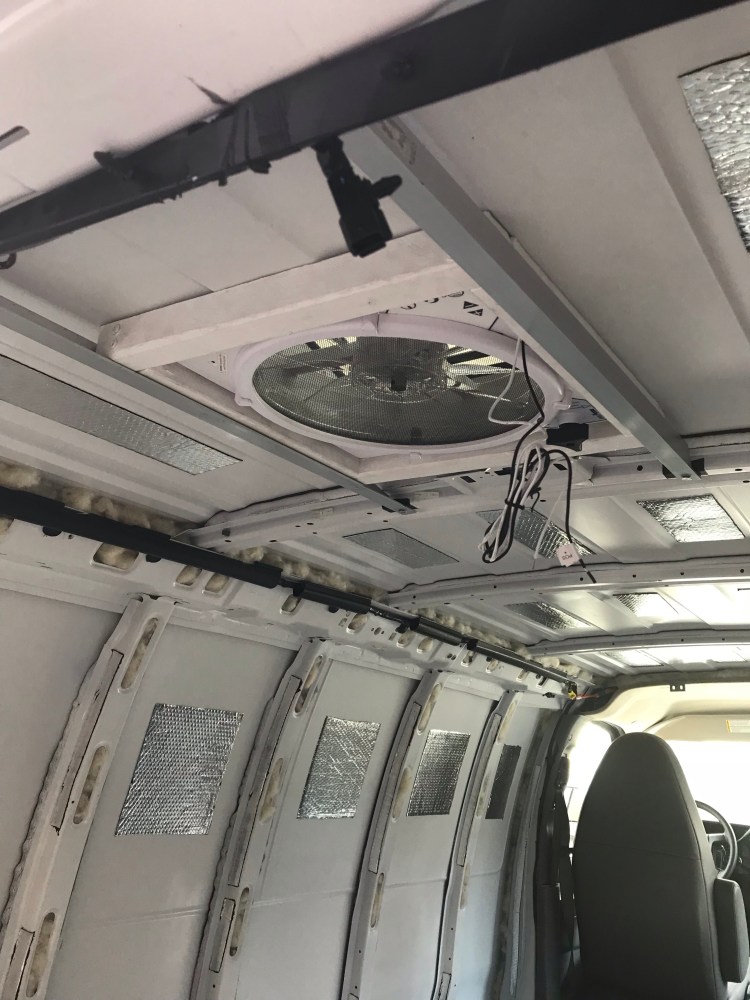
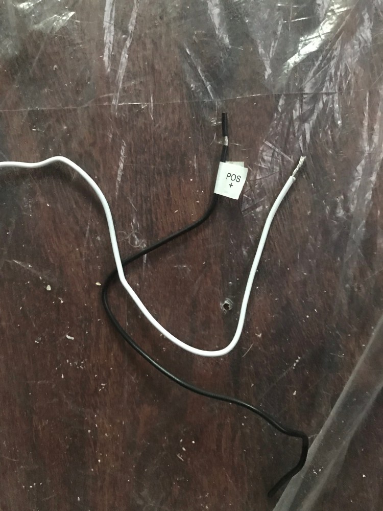
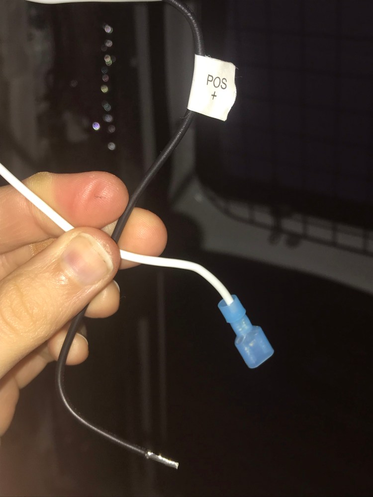
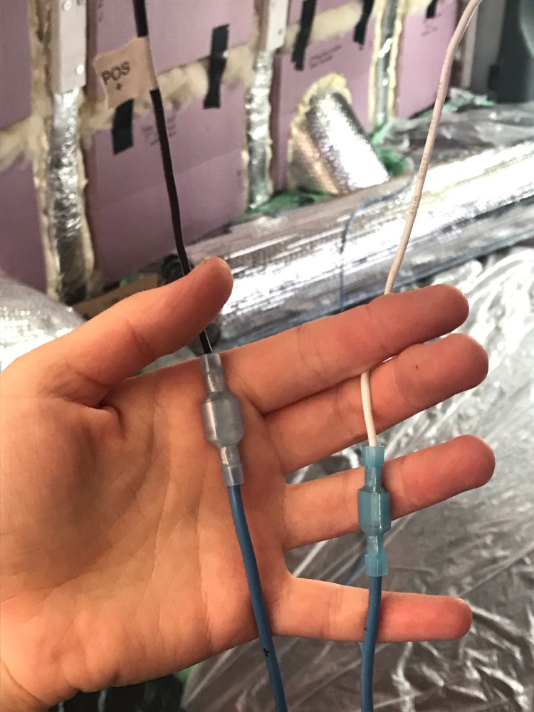
*In terms of wiring the MaxxFan, I used 1/4″ quick disconnects (a form of crimp connector) between the fan’s wires and 14AWG wires (the MaxxFan also came with some of these for this purpose). I have a tool for crimping/ stripping/ cutting wire.
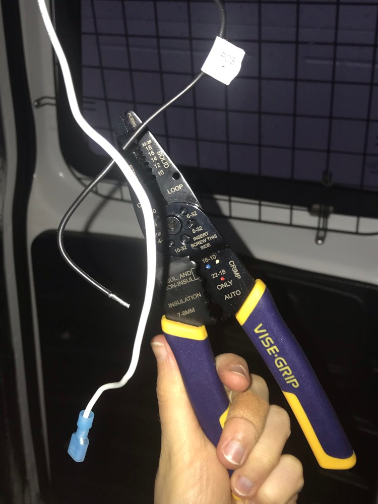
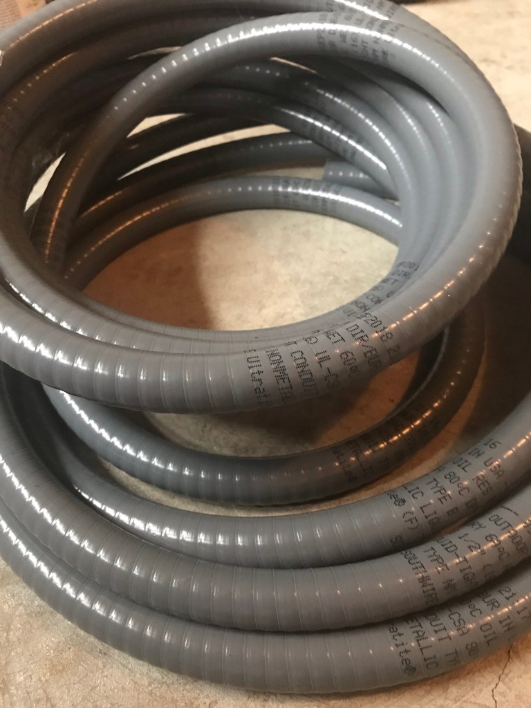
While I initially looked into more heavy duty conduit for the wiring, the type I got – although advertised as flexible – was definitely not as flexible as I needed it to be (it’s main purpose is probably for use underground). So I opted for some simple corrugated split tubing found in the car section of Canadian Tire.
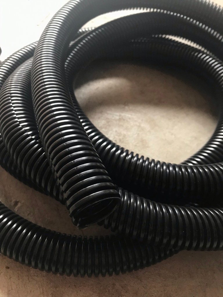
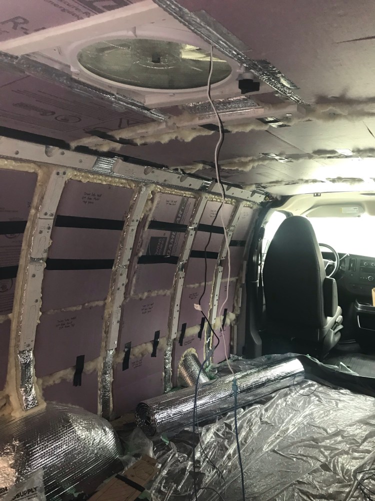
I used permanent marker to label my positive and negative fan wires and then fed them through this “conduit”. Then I snaked the wires and tubing between the rigid foam insulation and van ribs, keeping it above the level at which the ceiling would be installed, and securing it with Gorilla tape (plenty strong considering the lightweight nature of the conduit and wires).
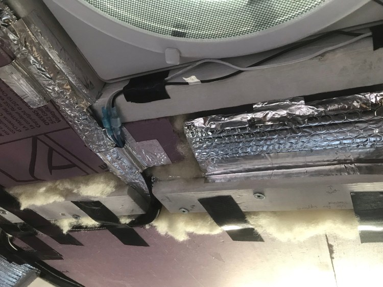
Some conduit tips include using it to secure wires to reduce excessive vibration which could damage wires and loosen connectors, and to fill the inner diameter of the conduit a maximum of 40%.

I purchased some heat shrink tubing in case of any exposed wire. To connect the wiring to the Yeti I will be using Anderson PowerPole connectors. I also plan on using a 10A fuse for the fan with an in-line fuse holder, installed near the battery (Yeti).
*Since I am thinking of changing panels and may want my set up to be mutable, I will likely re-do calculations to determine wire lengths, gauge, fuses, and connectors for the solar. I will update here when that happens.
Other Nifty Info
- Just out of curiosity, at some point in my research I was looking into what a solar panel (rigid) can handle, weather-wise. And apparently they can withstand hail – just not tennis or baseball sized hail!
- There is always more info on how to mount your panels, and everyone’s method tends to vary a little. Here is another article I found informative (including a blurb on tilt mounts so you can angle your panels toward the sun to get the most out of daylight hours).
- Speaking of weather – when it comes to solar panels one might think the more sun the better – but rain has advantages, too, in that it will clean your panels for you, removing dust and debris, in turn helping them function at their best.
- The Goal Zero Yeti has some built in surge protection. This is useful and also something I don’t have to worry about as much since I won’t be plugging into external power sources (like some RVs do), where I might be thinking about quality of the source or storms.
- I briefly mentioned cable entry housing above. One reason why this is a great addition to a solar set up is that if the cables from solar panels are left loose between the panels and roof (where they enter into the vehicle), they will be more prone to movement – vibration from the vehicle and wind. With this movement they could pull at your sealant and create a leak. The entry housing gives a second layer or protection from leaks and keeps the cables stationary where they enter the roof. Another option would be to use Eternabond tape to hold the cables against the roof – but not everyone wants such a permanent installation (though there are ways to remove Eternabond).
- Something else to consider with any external van application is weather resistance. Do materials hold up against water and UV rays? As well as theft deterrents – perhaps metal zip ties or locks on the panels.
All in all, I’ve got a few things left to research and then I just need to “connect the dots”. Once I do, I will update this post!
As always, I leave you with some music relevant to the build…
Later,
K
Copyright © Chronic X-Roads 2020

One thought on “Van Build #6: Solar”